|
|

|
|

|
|
|
|
|
|
|
|
MOOG MODULAR OWNER'S MANUAL by Dan Wyman, Sound Arts, Los Angeles for moog music, inc - 1981 |
|
|
|
|
|
|
|
|
|
|
|
|
|
MOOG MODULAR OWNER'S MANUAL by Dan Wyman, Sound Arts, Los Angeles for moog music, inc - 1981 |
|
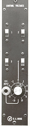
992 CONTROL VOLTAGES PANEL
The 992 Control Voltage Panel is used for routing control voltage signals (generally from Keyboards and Ribbon Controller) to filters and upper console modules in larger modular systems. The fourth input on the panel face contains a signal inverting attenuator circuit. |
|
993 TRIGGER AND ENVELOPE VOLTAGES PANEL
The Trigger and Envelope Voltage Panel is a signal routing module for S-triggers coming from one or two controllers. Lighted switches labelled "from 1" or "from 2" at the top of the panel connect the controller trigger outputs (when lighted) to the 911A Dual Trigger Delay. The lower three left hand column switches route the trigger signal as follows: top switch - to left 911 with no delay, center switch - to center 911 with delay set by top 911A delay unit (if any), bottom switch - to the right 911with delay set by the bottom 911A (if any). The right hand green switches connect the DC control voltages from the 911's to their respective 902 Voltage Controlled Amplifiers: Left to left, center to center, right to right. Any of these routes may be connected at the same time. |
|
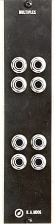
994 DUAL MULTIPLE PANEL
The dual multiple panel consists of two sets of four phone jacks. Each set of jacks has been wired together: tip to tip, sleeve to sleeve.
FUNCTION DESCRIPTION/APPLICATION |
|
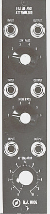
995 ATTENUATORS
The 995 Attenuator panel consists of three "passive circuits", each made of a 25k potentiometer between input and output. The signal input to the top attenuator is chained to the bottom two in series. Introduction of a phone plug into middle or bottom input breaks the normalling system: 1 to 1-2-3, 1-2 to 2-3, 1-2-3 to 1-2-3. The CP35 functions in the same way, but with 4 inputs - a chain of 4.
FUNCTION DESCRIPTION/APPLICATION |